
|
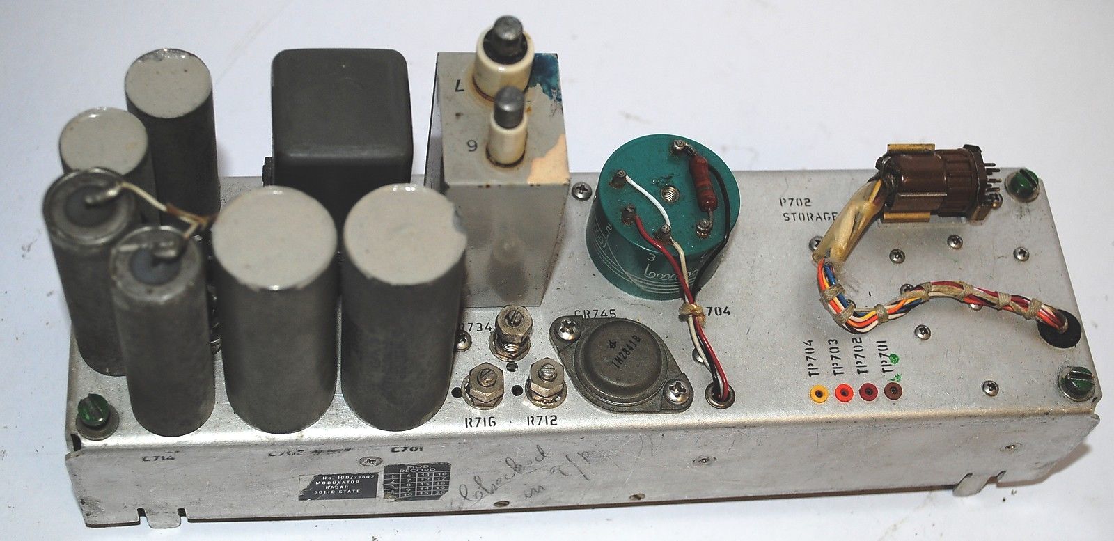
The ARN-21D was introduced in 1961 and was the first with A/A mode. To handle the 4x higher average transmitter power, the AN/ARN-21D has a solid state modulator for 1050 pulses/sec. This modulator has two pulse forming networks, each PFN is charged in 100 us, to guarantee the minimum pulse distance of 125 us.
The ARN-21D was introduced as an upgrade kit for the ARN-21B or –21C. The kit contains the solid state modulator, a relay, wire, and a new mode switch + bezel for the cockpit control panel
The kit is described in MIL-M-22965A(WEP) and in patent US3076190. These can be downloaded for free from the Mil docs server or a patents server I got a picture from the ARN21D = ARN72 , photo courtesy Nick Vernon.
The ARN21D modulator circuit diagram and some info is here.
The ARN21 series require an external indicator coupler like the CU-395 /ARN to drive the Course Deviation Indicator ( ID-249 ) and the Radio Magnetic Indicator ( like ID-250).
The original ARN21 was made by Hoffmann , Federal (ITT) and Stromberg-Carlson . Collins also entered the ARN21 market in 1956 with the ARN21 (XN-10), an ARN52-like box, soon followed by the TCN-101 in 1957. Their brochures , including the indicators are on the RockwellCollinsMuseum site.
In 1960, the ARN-21 series was followed up by the ARN-52, which supports the A-A mode, and had built-in indicator couplers. Like the ARN21D, the ARN-52 has two solid state modules, the power supply and the modulator. All other modules have (lots of) tubes.
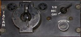
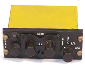
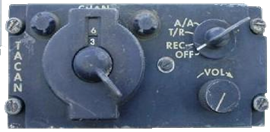
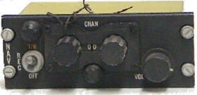
Control panels From the beginning, control panels had two versions, “NAV” and “TACAN”. They were fully compatible, with only minor differences in the volume pot and bulb voltage The following control panels were used for the AN/ARN21 series:
Top C 866 and C 1763 Only REC and T/R modes) Bottom C 3844 and C 2010 with A/A mode
When the C866 and C1763 were modified as an A/A upgrade, these control panels became C866A or C 1763A. |


|
A tribute to its inventor, Sven H. Dodington. |
|
VINTAGE AVIONICS |
|
Other ARN21 versions |
|
History TACAN as introduced in 1954 had 126 channels and used twin pulses, separated by 12us, both for uplink and downlink. Later on these were called the "X" channels. The aircraft unit transmits on one of 126 channels 1025 … 1150 MHz, and receives for the first 63 channels on 63MHz below the transmit frequency, but for the upper 63 channels on 63 MHz above the transmit frequency. The below/above selection is done by solenoids in the preselector cavities. All "X" ground beacons are outside the 1025 … 1150 MHz band. The ARN/21 A, B and C have these 126 transmit and 126 receive channels. This changed with the introduction of the ARN/21D, which could receive on all 252 channels, 126 from the ground, and 126 from other aircraft.
A/A mode By swapping the preselector control wires, any ARN21 can also receive inside the 1025-1150MHz band. So another aircraft can be received that is 63 channels above or below its "own" channel. This swap was introduced as A/A mode in the AN/ARN21D and provided for the “bilateral range function”. Each aircraft with this function is both an interrogator and a transponder. As an interrogator, each aircraft transmits the usual 15 or 150 twin pulses /sec As a transponder, each aircraft replies with a single pulse to let the interrogating aircraft find their mutual distance. The unit shall : a) receive twin pulses, and reply each after 50us with a single pulse , except b) the single or twin pulse that coincided with its range gate is not retransmitted, but used to track the displayed range. With up to 5 aircraft nearby, all in "search" mode, 750 (single) pulses/sec must be transmitted on top of the usual 30 or 300 pulses/sec to interrogate the ground beacon.
Y channels. In 1965 , the number of channels was doubled to 126 X and 126 Y channels. Also, ground beacons inside 1025 … 1150 MHz were allowed. To distinguish these Y-beacons from X-channels or aircraft on the same frequency, specific twin pulse separations for the Y channels were chosen. Seen from the aircraft, these are:
Versions There are 4 American and 1 British versions of the ARN21 airborne navigation set.
Version Year Tubes AN/ARN-21A 1954 73 With Ferris detector. STARN-21 1955 106 British version of the ARN21A made by STC AN/ARN-21B 1956 76 See this site AN/ARN-21C 1960 56 All vacuum diodes or triodes used as diodes are replaced by si diodes. Turret got full 126 Xtals AN/ARN-21D 1961 52 Has Air-Air mode, (still only X channels). Upgrade from = ARN-72 21C by replacing the modulator for a solid-state one. Also known as ARN-72 (thanks, Nick)
The ARN-21A was the first TACAN set . I have no circuit drawings of this unit, but it is probably close to the British STARN21. Both had a Ferris detector to reduce interference from first generation beacons on neighbor channels.
The ARN-21B is described on this site. See the diagrams with explanation and screenshots on the second page of each pdf file.
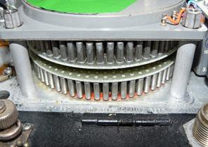
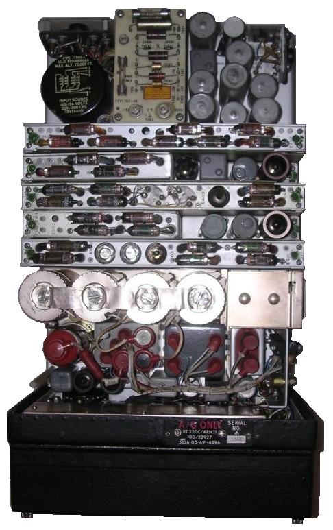
The ARN-21C was introduced in 1960. Mainly value engineering, the functionality is the same as the B version. The C version has a lower tube count, and less spurious emissions than the B version. Less tubes means less heat, less power consumption. The power supply unit is fully solid state. The MTBF went from 20 to 200 h. The turret got 126 crystals (!) , one for each channel. This eliminated the 42 MHz oscillator and mixer, and the 42MHz sidebands. Further, a 1300 MHz lowpass filter was added in the antenna connection to filter the second harmonic.
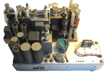
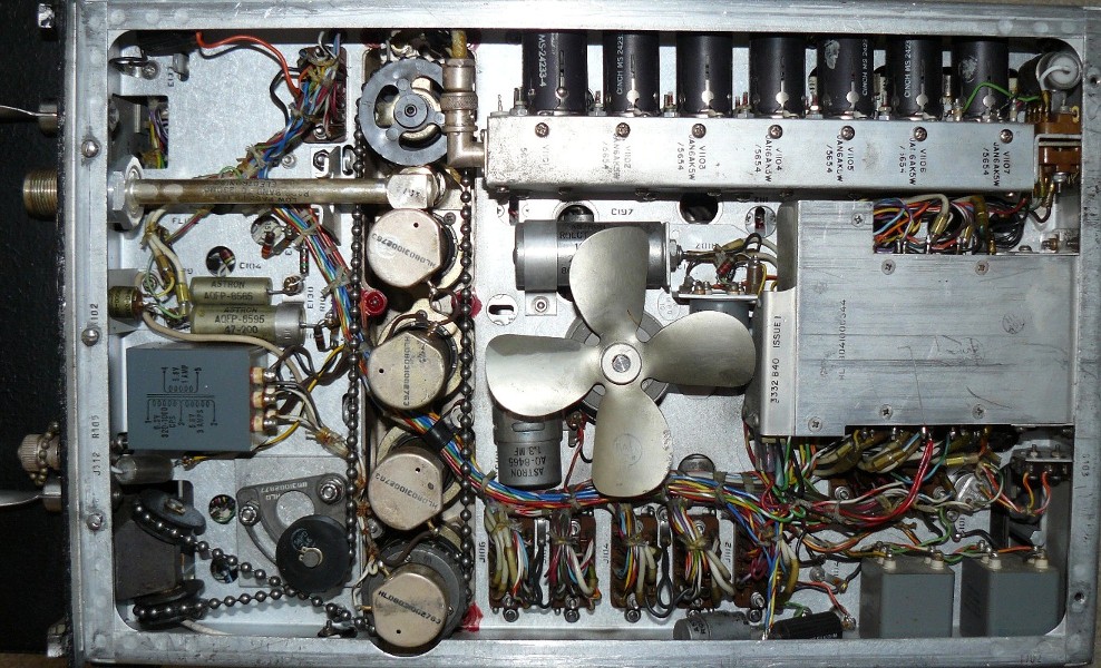
<—-Turret with 126 crystals in the ARN21C The top view of the complete unit is here. A wiring side view is here Photos courtesy Bryan Seeds, vintage avionics site |
|||||||||||||||||||
|
The modulator of the ARN21B (rear) and the ARN21D ( in front) |