

|
Many post-war avionics use 115Vac / 400Hz. The AN/ARN-21 requires 115V/400Hz at approx. 2.7A (310VA) plus 27Vdc/1A for relays, panel lights and the channel selection motor.
Problem is: how to get 400Hz ?
I could get a PS4060 power supply from a Compaq Proliant server. This PSU can convert 500W at any input voltage 100V ... 245V ac into 12Vdc, 5Vdc and 3.3Vdc. These servers are now gradually phased out, and the PS4060 power supplies become available on the surplus market.
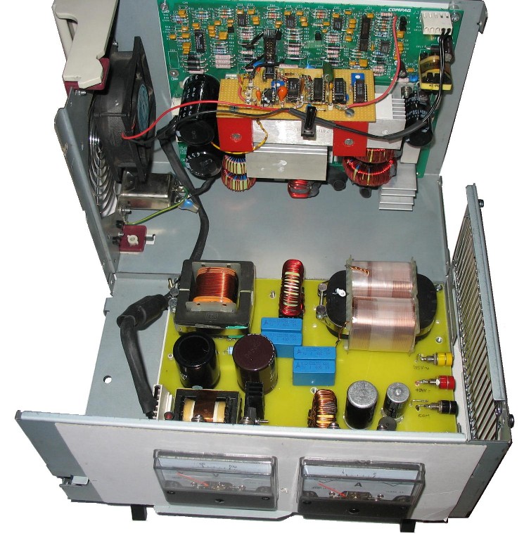
The PS4060 has a convenient box with lifting handle, containing 3 boards : the primary circuits, the secondary circuits, and the hot-swap controller. From these, the primary circuits board, box, and the fan were re-used. A new secondary board and a controller are needed to generate a 400Hz sine wave instead of 3 different dc voltage outputs.
The primary board has extensive EMC backfeed filtering, even a power factor correction (PFC) chopper that provides 382V dc. There is also an 18W auxiliary dc/dc converter providing +15V for the mains-side electronics, and +9V which I used for the fan. This fan with a 10W brushless-dc motor ran originally from the 12V output bus -like a hurricane. Running from 7.5V reduces the noise and still gives sufficient airflow to keep any component below 50°C at the 75W dissipation inside the box. The efficiency at 300W output is 80%. (60W losses ! )
The circuit diagram and description of my 400Hz converter is here The PS4060 single line diagram is here. The primary board in detail can be found here.
The basic circuit is a half-bridge inverter with 2 of the 4 power fets IRF PG50 on the primaries board. As their intrinsic body diode is slow, freewheel diodes are added in parallel with the fets. The other half of the bridge is a couple of 220uF electrolytic capacitors. The 18kHz PWM wave is filtered to a 400Hz sine wave with a low-pass filter. The series choke is 2mH, the capacitor is 4uF. Half of this capacitance has a 40uH series choke to form a notch filter at the PWM frequency, reducing the PWM component in the output to <1%. Finally, a C-core output transformer with 1:1 winding ratio provides the separation between mains and output 400Hz circuits. Especially because in many avionics one side of the 400Hz input is connected to chassis. The outputs of the unit are on the right-hand side.
Two things were of great help in this application. First, the 200W of heaters in the TACAN set are a resistive load for the output filter, and give good damping on the main resonance. Second, the PFC chopper gives 382V output at any load with little ripple, so a pure open loop PWM wave is sufficient to provide a reasonable stable 115Vac on the output.
The components of the original 12V output of the PS4060 can be re-used for a 24V output. I transplanted the transformer and one of the rectifier dual-diodes of the original 12V output of the PS4060 to the new secondary board. Without feedback, the dc output voltage is 23V at 3A, sufficient for the tacan set..
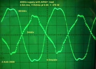
Results The output approximates a sine wave. Shown next are the voltage and current of a full running ARN21 (except modulator tube 3D21) on this 400Hz converter.
The dip near the top is an interaction between the output filter in the generator, and the dc rectifiers in the Tacan set. Although the distortion on a 300W resistive load is 4%, with this non-linear load I got 9% (see picture) Without any load, the distortion is 8% due to lack of damping on the output filter.
This is with a slow voltage control. Probably a fast full sinewave voltage control will improve the distortion.
The sound level is 60 dBA at 1 meter, or 66 dBA at 35cm, which is the noise from the fan, the 800Hz whine from the output transformer, and 17kHz from the filter choke.
The mass of the complete 400Hz converter is 5.5 kg, and the size is 300 x 135 x 200 mm including handle and stand-offs |

|
Click the picture to open the box. |


|
VINTAGE AVIONICS |
|
A 400hz converter |