|
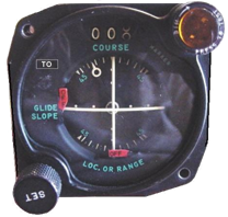
Course Deviation Indicator ID-249 |
|
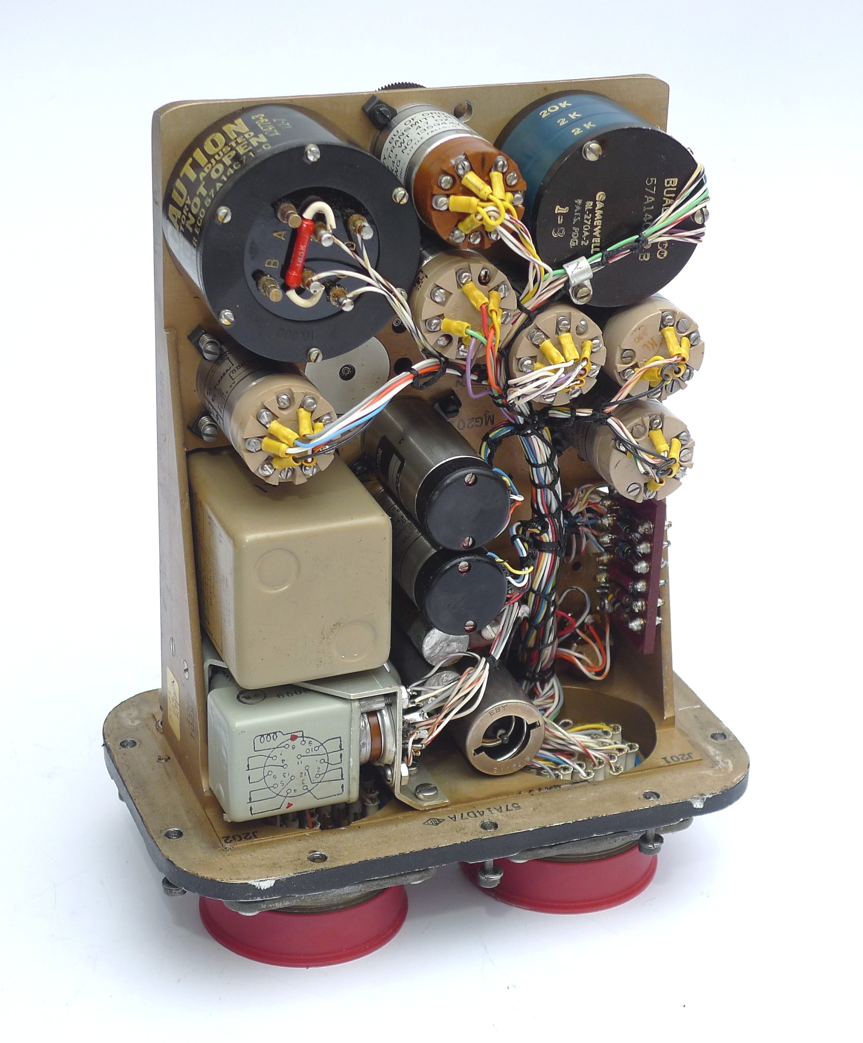
Phase Detecting Network CV-279 (click for open unit) |
|
Indicator Coupler CU-395/ARN21 Click in picture to open the box. Photo courtesy Anton Hermans |


|
VINTAGE AVIONICS |
|
Course Indicators |
|
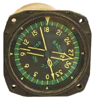
The azimuth and range indicators ID-307 and ID-310 were introduced with the ARN-21A in 1955. The basic “Radio Bearing” of the ID-307 has North always on the top of the dial which is not very intuitive. The ID-307 therefore has two built-in synchro’s to present the TACAN information on the earlier VOR indicators. These are the Course Indicator (now called Radio Magnetic Indicator or RMI ) ID-250 which has 3 synchro motors. One rotates the compass dialcard such that the flight direction is on top, the others drive pointers. Pointer 1 can be connected to the differential synchro from the ID-307 and then points in the direction of the TACAN beacon, while pointer 2 can point to a VHF OmniRange beacon (VOR) or to any radio station using an automatic direction finder (ADF) and a suitable receiver. VOR and Localizer beacons were received with a separate receiver plus a special converter to drive the indicators. These indicators have round plugs. It is possible to make a homebrew cable part
The other instrument is the Course Deviation Indicator or CDI. The ID-249, or the plug compatible ID-351 or ID-387 show the deviation from a preset course. The SET knob is used to set the desired track to be flown into a COURSE window; an adjacent TO-FROM window shows that the selected course is either toward or away from the selected beacon. The course indicator also contains two bars and a pointer. The vertical bar moves from a center position to either the left or right, indicating the on-course or off-course condition of the aircraft with respect to the selected course. set The horizontal bar is driven by the instrument landing system (ILS), indicating whether the aircraft is above or below the ideal glide slope. The white circle pointer (relative bearing indicator) presents the angular difference between the magnetic heading of the airplane and the preset course. Two red warning flags, labeled OFF, are associated with the vertical and horizontal bars and come into view whenever the equipment operating their respective bars become inoperative or the received signal is weak or unreliable. A marker beacon light is located in the upper right-hand corner of the indicator case.
The ID-249 has 5 “moving coil” type actuators, each with 1 kOhm dc resistance and approx 300uA sensitivity. They drive the two needles, two alarm flags and the TO-FROM indicator. Further there is a synchro to transmit the set course to other instruments, a synchro to drive the relative bearing pointer, and a resolver to compare the preset course with the actual course. This resolver requires a few electronic components to feed the result to the vertical bar(Localizer) and the TO-FROM flag. These electronics are housed in the CV-279/ARN Phase Detecting Network which combines the inputs from the fundamental resolver of Azimuth Indicator ID-307/ARN and the course selector synchro resolver of the ID-249. The unit operates the vertical pointers (left-right) and ambiguity meters (to-from) of one or two deviation indicators and the automatic pilot. The COURSE WIDTH sensitivity adjustment is on this unit.
The diagram of the ID-249 is here
The interconnection diagram that I compiled from many bits and pieces, including the diagram of the CV-279 and ID-250 is here. Note that although there are many 3-phase (400hz) synchro motors in the circuit, the only power supply needed is a single-phase, 26V/400Hz source, capable to produce 1A rms. I do not have the ID-249 nor ID-250 so I am not sure whether the details are correct
The CU-395 Indicator Coupler In the interconnection diagram you can see that the ID307 is only used to convert the bearing from ARN21 signals into synchro signals, the indicator scale of the ID-307 itself is not used.
For this reason, a boxed version of the ID-307 and ID-310 was introduced in 1956, the CU-395 Indicator coupler. The box has two male 47-pole connectors, one for the inputs from the ARN21, and a rotated one for the output to the ID-249 and ID-250. The (incomplete) diagram is here.
|
|
Radio-Magnetic Indicator ID-250 |
Vintage Course Indicators |