
|
Communication |

|
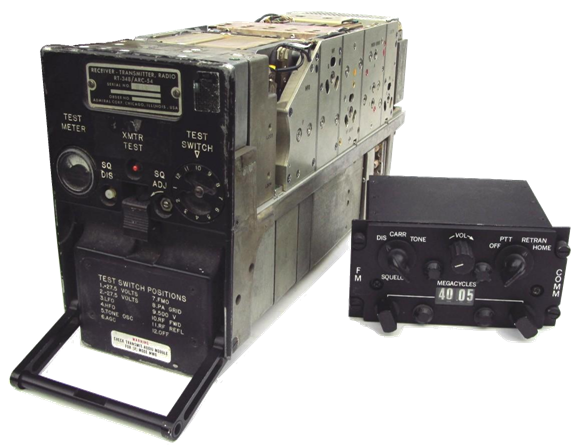
RT 348 ARC-54 with C 3835 control |
|
1960 |


|
VINTAGE AVIONICS |
|
AN/ARC-54 FM LIAISON SET |
|
Radio Set AN/ARC-54, made by Collins, is a lightweight FM airborne radio set , designed for use in aircraft for air to-air and air-to-ground communications, CW homing and airborne retransmission .
The AN/ARC54 is capable of transmitting and receiving on any one of 800 channels, spaced 50 kHz, within the frequency range of 30.00 to 69.95 MHz. Frequency deviation is 8 kHz narrow band; 20 kHz wide band. The power output is > 10 watts. Input power requirement is 28 Vdc at 5 amps during transmit or 2 amp when receiving.
This successor of the ARC-44 now includes the power supply, homing keyer, and test meter inside the unit The ARC-54 is a double superhet with 20 Xtalls in the first oscillator, and 20 Xtalls in the second oscillator that are used twice: below and above the first ( variable) IF to produce the fixed second IF at 500 kHz. This gives 20 x 20 x 2 = 800 channels. The receiver-transmitter has 3 tubes and 46 transistors, mainly 2N338 in the low frequency modules, and germanium PNP ( 2N1225 and 2N2996) in the RF stages and oscillators.
Components of the AN/ARC-54 are: RT-348/ARC-54 ............. Receive-Transmitter C-3835/ARC-54 ................... Control MT-1535 / ARC-54 ……. Mounting CU-942 or CU-943 …….. Antenna coupler (motor tuned ) in whip base. AS-1703……………….. .. Communication (Whip) antenna mounted on coupler. AS-1922 ……………………. Homing antenna ( towel rack)
The connectors on the ARC-54 and ARC-131 receiver/transmitters, and on their control panels are identical, but the control panels cannot be exchanged because the coding of the MHz selector is different. More information on the FM control panels here. And a picture of my control panels collection.
Homing Requires a homing antenna and the cross-pointer indicator ID-48. The vertical needle indicates the direction of the source, the horizontal needle indicates the signal strength. Read more ..
Circuit diagrams : All circuit diagrams C-3835 control panel and interconnections
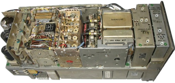
Top view of the Collins-made RT-348 / ARC-54 without covers. From left to right : the RF power amplifier, mechanical tuner, RF stages, Variable IF Amplifier, High and Low Frequency Oscillators, Homing circuits, and Squelch circuits. On the underside of the central septum are the antenna harmonics filter, power supply, Rx and Tx audio modules, and the fixed IF amplifier. |
|
FM Communication
VHF Communication
UHF Communication
|
