

|
Controls
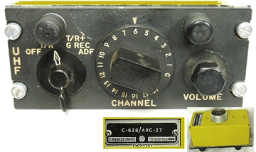
The first generation controls for the ARC27 came in two boxes– one to store the 20 preset channels in motor operated drums, and a second one to select one of them . The C-626/ARC-27 stores the presets and the C-628 ( shown here) selected one of them. The interconnections for these panels are shown here
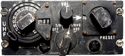
Later came the all-in-one control panels like the C-1702 shown . Any frequency ( out of 1750 channels) is selected on the dials to the right with the left dial set to “M”. A manual selected channel can be stored when the red “program” button is turned to set the pegs on the memory drum. This early control panel works pretty the same as what you see on modern radios and TV sets! The circuit diagram of the C-1015/ARC27 is a compact version of this C-1702. The connections to the RT-178 is here.
A more compact version of this control is the C-1904. (shown left) The functionality is roughly the same, except that the pegs could only be set from the rear side of the control, prior to flight.
|
|
Communication |


|
1950 |

|
FM Communication
VHF Communication
UHF Communication
|


|
VINTAGE AVIONICS |
|
AN/ARC-27 |
|
Radio Set AN/ARC-27 was the first UHF radio set, designed for use in aircraft for air to-air and air-to-ground communications.
The AN/ARC-27 is capable of transmitting and receiving on any one of 1750 channels, spaced 100 kHz, within the frequency range of 225.0 to 399.9 MHz. Audio Frequency bandwidth is 6 kHz , audio output is 2W. (0.5W at 10% distortion) The RF power output of the AN/ARC-27 is 9 watts Input power requirement is 28 Vdc at 19.1 amps during transmit or 16.5 amp when receiving. During channel switching, the dc current rises to 25.5A, with 200W dissipation in the remote storage drums box C-626/ARC-27. The ARC-27 is capable for 1020 Hz tone modulation. Weight is 71 pounds ( 38 kg) ….
Major components of the AN/ARC-27 are as follows: RT-178/ARC-27 .............. Receiver-Transmitter C-626/ARC-27 ................... Control ( with optional MT-821 mount) MT-822/ARC-27 ……...... Mount AS-390/SRC …………... .. Stub Antenna AN/ARA-25 ………….. … Automatic Direction Finder
The Historic Naval Ships Association has an equipment list, with more details of the ARC-27 like the tube line-up. Also on this site are details for the AN/ARA-25 automatic direction finding antenna, often used together with the AN/ARC-27. How it works. >>> All Circuit Diagrams of the ARC-27 can be found here. The ARC-55 is the non-pressurized version of the ARC-27 |
|
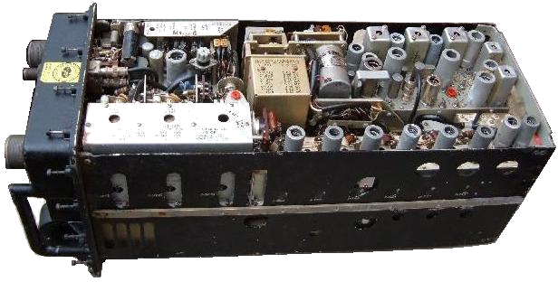
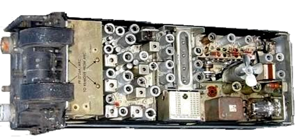
RT-178 / ARC-27 top and bottom ( 1950) Top > left the RF power amp (with 2x 2C39A), the relays, in the middle the boxed third local oscillator with motor, guard receiver and spectrum amplifier. Bottom > Fan, left the boxed dynamotor, the third IF and audio amplifier , the first and second IF with crystals box for the second LO, the RF preamp, the spectrum oscillator at the far right, and the modulator with 829B. De complete set has 55 tubes, and no transistors. |
AN/ARC-27 UHF Airborne Transceiver ( 1951 ) |