


|
A tribute to its inventor, Sven H. Dodington. |
|
VINTAGE AVIONICS |
Beacon SimulatorI have built a simple beacon simulator to test the ARN-21. Because this vintage TACAN set only has X channels, the simulator only produces X mode signals, i.e. twin pulses with 12 us spacing, 30us pulse spacing for the main ref group etc.
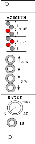
The simulator is supplied from +28Vdc, and provides a composite video signal with 15Hz and 135Hz amplitude modulated twin pulses, made-up of the main and aux ref groups, squitter, and -of course- the reply to the interrogation impulse of the set, which is tapped from the blanking output on the front of the ARN-21. Both bearing and distance can be set at will.
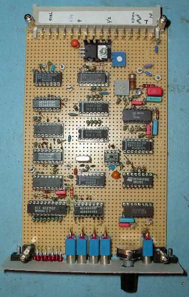
Circuit diagram is here
The basis for all timing is a single crystal at 4 MHz. This frequency is divided by 2963 to get almost exactly 1350Hz. Division by 10 and 9 gives the auxiliary and main reference bursts at 135Hz and 15Hz. In a second divider, the 4MHz is also divided by 2963, but as long as one of the azimuth up/down buttons is pushed, the divisor is slightly different. The resulting 1350Hz +/-something is divided down to 135Hz and 15Hz, in sequential counters, the outputs of them are summed up to get two sine waves. These are added to provide the typical pulse amplitude modulation of a TACAN signal. A 63 “random” numbers generator is used to make the squitter pulses. The RF modulator from a video recorder (VCR) is well suited to give this beacon simulator a RF output as well. Most VCR modulators can be tuned at 540-634 MHz, and the second harmonic covers the full high TACAN band of 1088-1213 MHz.
This single-board beacon simulator is a lot smaller than the 5 ft tall simulators that were used in 1955 ! |
|
TACAN Beacon Simulator |